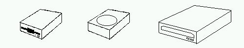
The Disk Drives
- Instalation of FDD Usualy they are 1.44 Mb 3.5 inch in width. Secure the drive in the case with screws. Connect the power cord and the 34 wire data ribbon to the end of the drive, (red wire stands for pin 1) pin 1 twoards the power connector. At the motherboard pin 1 where it is marqued usualy with "1".
NOTE: at one end of the data ribbon there is a 7 wire strip that is twisted. This end to the floppy drive. It stands for the first floppy drive, the one the computer can boot from. If you place the drive on a untwisted connector, this will be "floppy drive B" and older motherboards cannot boot it.
- Instalation of IDE devices Most motherboards have two IDE channels. This means you can mount up to 4 IDE devices on it. Each channel suports two drives (one master, one slave). When one installs two drives on the same channel one should be master and the other should be a slave. It does not matter where on the cable you place them. Common practice is: HDD is the master and the CD-ROM is slave. Make the jumper settings (jumpers are usualy at the rear of the drive) accordingly, screw them in (HDD is a sensitive piece of equipment, so you have no toruble, mopnt it with the circuit board facing down), have the cords and ribbon connected and from a hardware point of view it is all set.
NOTE: There is a "Cable Select" option in the IDE drive's jumper settings. Try to avoid it for reasons of simplicity.
<-Back written by Nagy Andrei (27apr2003) www.yioth.3x.ro
Next->