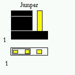
A jumper as shown in the picture, is an "utility" that is used to make hardware settings on a motherboard, expansion card, hard disk and so on. A jumper has basically two components: the pins, soldered on the circuit card and a "cap" that can be removed and/or set to short the pins. When making jumper settings, make sure that the machine has been plugged out and there is no danger of electric discharge. Be aware that static electricity stored in one's cotton sweater is enough to fry sensitive memory modules; so proceed with caution.
When dealing with jumpers you must have some sort of a table available. Ususually printed in the Motherboard User's Manual or on the circuit board. If you don't have such documentation it's imperative to get it. Try to find out the motherboard's manufacturer and model. It is usually written down in paint somewhere on the printed circuit board with larger fonts. If that doesn't work out, locate two large chips (the chipset) and search in google for "
Below i've written an example taken from the VIA Apollo P5MVP3 Main Board Manual:
| CPU Bus | JP6 | JP7 | JP8 | JP10 | JP11 | |
| 60 MHz | 2-3 | 2-3 | 2-3 | 2-3 | x | |
| 66 MHz | 1-2 | 2-3 | 2-3 | 2-3 | x | |
| 75 MHz | 2-3 | 1-2 | 2-3 | 1-2 | 1-2 | |
| 83 MHz | 1-2 | 1-2 | 2-3 | 1-2 | 1-2 | |
| 95 MHz | 2-3 | 1-2 | 1-2 | 1-2 | 2-3 | |
| 100 MHz | 1-2 | 1-2 | 1-2 | 1-2 | 2-3 |
So if i have a Cyrix processor for example, i know it's bus frequency of 60 MHz. First step is to locate the jumpers mentioned. Then, looking at the board, i identify pin 1 of each jumper (usually they have the same orientation) and set them accordingly. JP6's cap should short pins 1 with 2, JP7 shorts pins 2 and 3 (leaving pin 1 uncovered), when at JP11 remove the jumper completely and store it in my spare jumpers box.
<-Back written by Nagy Andrei (27apr2003) www.yioth.3x.ro Next->